Start by creating the Tank attachment angles
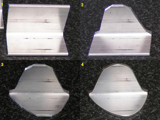
Here is the tank attachment angle fitted to the nose of the tank rib.
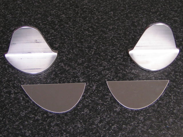
The tank reinforcement plates for the inside of the rib:
Drilling the tank fuel cap flange:
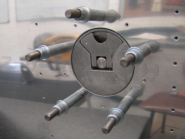
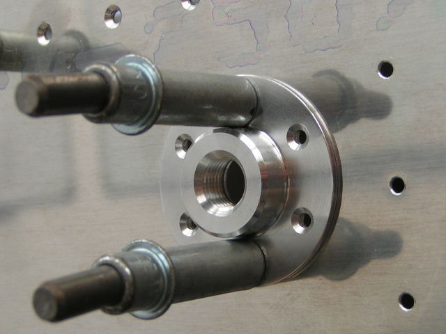
The tank drain valve fitting:
The tank stiffener ring around the inspection hole:

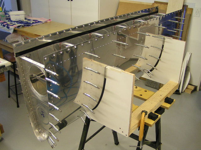
The two tank inboard ribs with the inspection hole ring reinforcements attached:

Making an attachment for the fitting the fuel sender in the second bay for inverted fuel system:

The fuel sender fitting cut out from the above plate:

Countersink the plate:

Align just next to the Z bracket

Mark and drill:

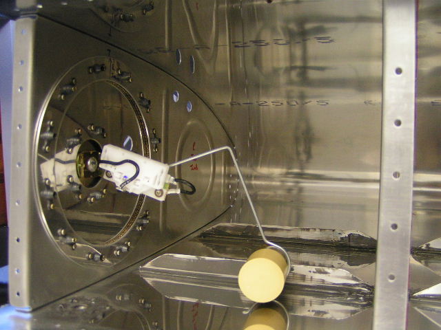
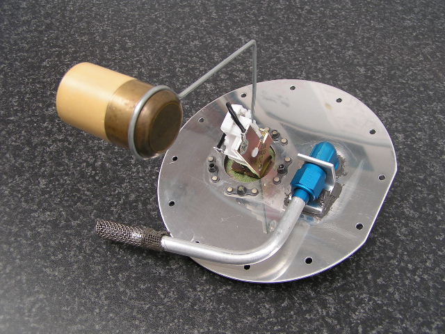
Test fit the fuel sender

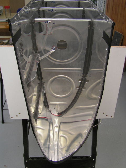
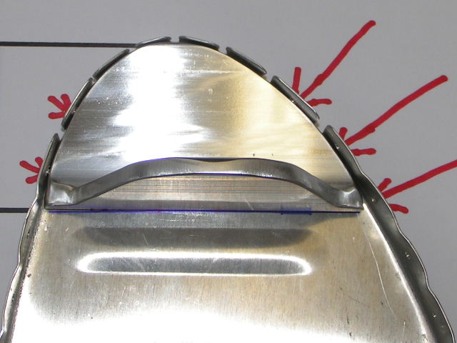
Test the flop tube fitting on the nose rib:

The other side of the flop tube fitting:

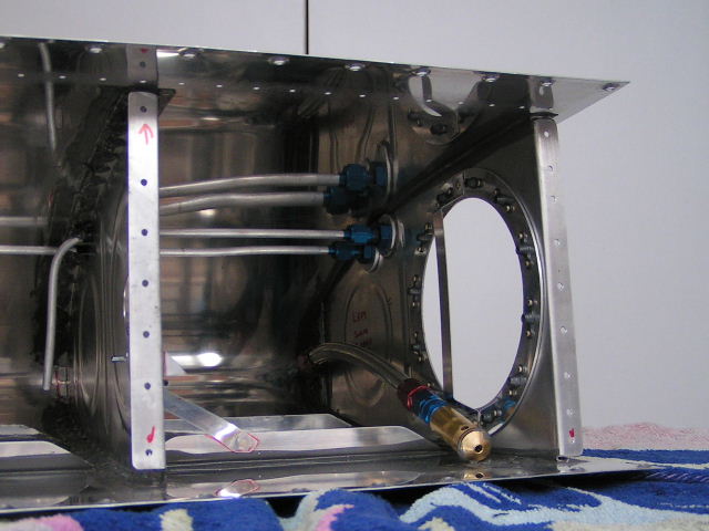
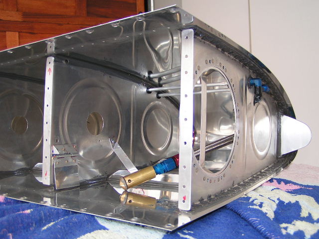
Position for the Tank Vent and Vapor Return lines:

A close up:

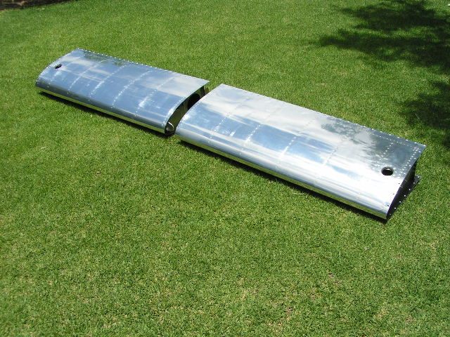
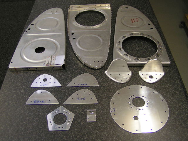
All the tank parts that needed some kind of manufacturing done to them:
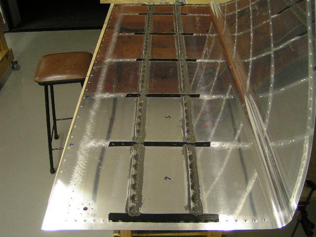
Scuff the tank where proseal is going to fit:

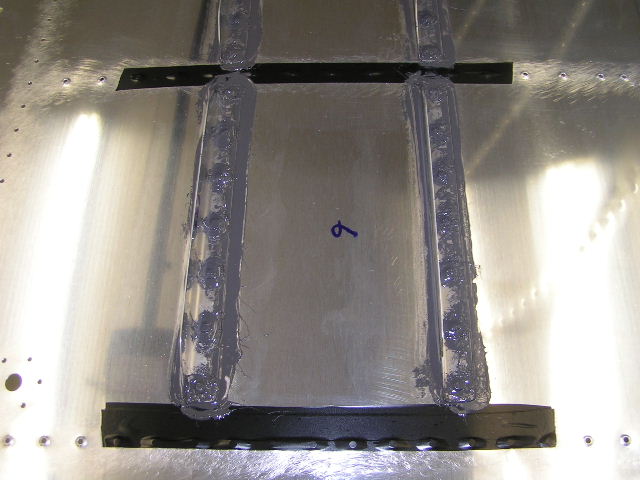
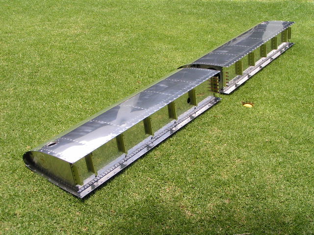
The Tank Stiffeners into place
Electrical tape over the areas that you do not want proseal over.